Hovercraft Software Design
1. Overview
2. Code Flow Diagram
3. Pairing State Diagram
4. Code Listing
a. Source Code - PIC16F1788
b. Header Files - PIC16F1788
c. Assembly Code - PIC12F752
d. Code Downloads
2. Code Flow Diagram
3. Pairing State Diagram
4. Code Listing
a. Source Code - PIC16F1788
b. Header Files - PIC16F1788
c. Assembly Code - PIC12F752
d. Code Downloads
Overview
Our hovercraft was controlled by a PIC16F1788 microcontroller chip. We programmed this PIC in C using an event-driven paradigm. In addition, there was an on-board PIC12F752 that controlled our electromechanical display of pairing status (the DMC). This smaller PIC communicated with the '1788 via the state of two digital I/O pins. The '752 was programmed in assembly language, as per one of the project requirements.
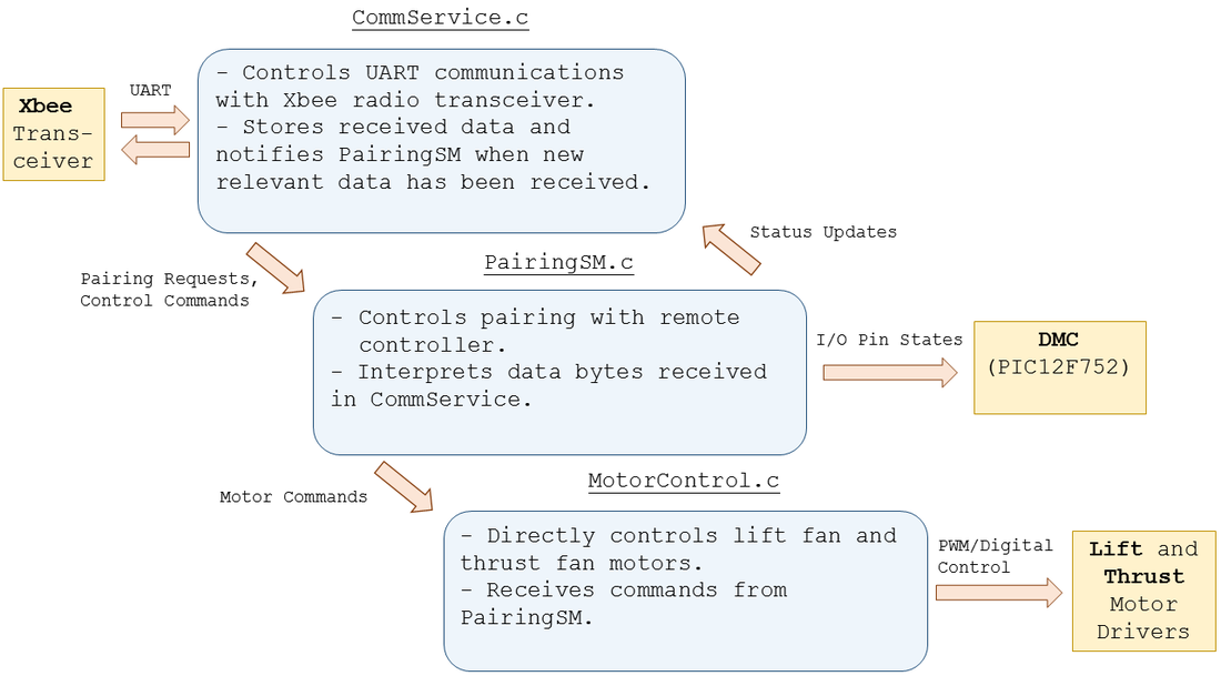
Code Flow Diagram
This diagram shows a high-level description of the code flow in our hovercraft's main microcontroller.
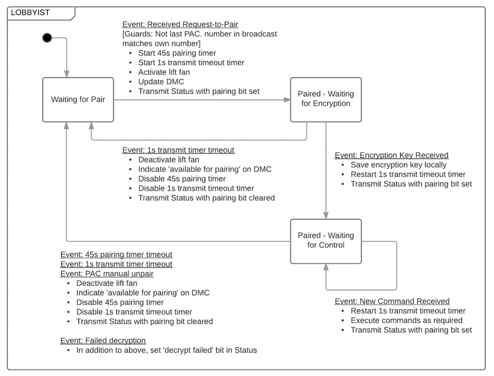
Pairing State Diagram
This state diagram illustrates how our "PairingSM" module handled communications with remote controllers. The diagram was developed by the class-wide communications committee.
Code Listing
Source Code - PIC16F1788
Header Files - PIC16F1788
Assembly Code - PIC12F752
Code Downloads
|
| ||||
