Hovercraft Electrical Design
1. Overview
2. Main I/O Board
3. Display of Memory and Commitment (DMC)
4. Motor Drivers
5. Power Distribution
2. Main I/O Board
3. Display of Memory and Commitment (DMC)
4. Motor Drivers
5. Power Distribution
Overview
The brains of the hovercraft is the PIC16F1788 microcontroller. The other modules onboard include the XBee for radio communication with controllers, the badge resistor for determining which number (1-4) our hovercraft is currently representing, the lift fan and two thrust/steering fans, and the display of memory and commitment (DMC).
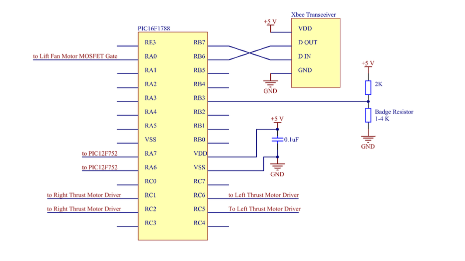
Main I/O Board
This is the central circuit of our hovercraft. It contains the primary microcontroller (PIC16F1788), which controls all other electronic modules on the craft. The badge resistor can have a value of 1 K, 2 K, 3 K, or 4 K, and the voltage at the voltage divider is read by an analog pin in the '1788 in order to determine which resistor is present.
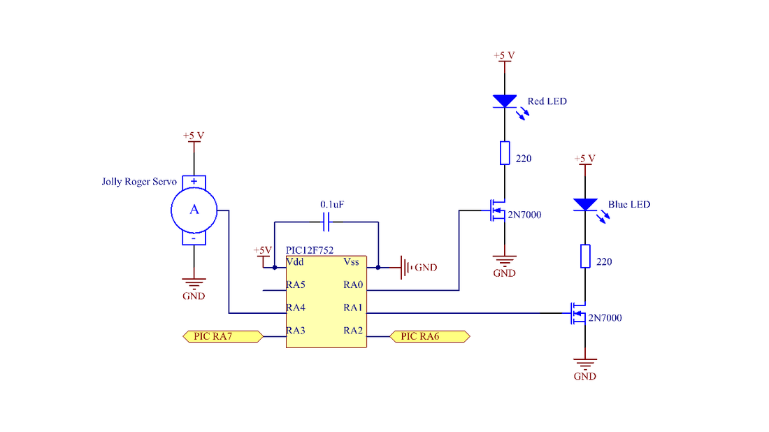
Display of Memory and Commitment (DMC)
One of the project requirements was that the DMC be controlled by an 8-pin PIC12F752 microcontroller programmed in assembly language. Thus, the DMC consists of the '752, a servo motor, and a couple of LEDs. As a whole module, the DMC constantly reflects the pairing status of our hovercraft. When the craft pairs with a new controller, the '752 commands the servo to raise a jolly roger flag to full mast. This flag slowly lowers throughout the 45-second pairing period. Additionally, the '752 commands red and blue LEDs that constantly indicate the paired controller's team color.
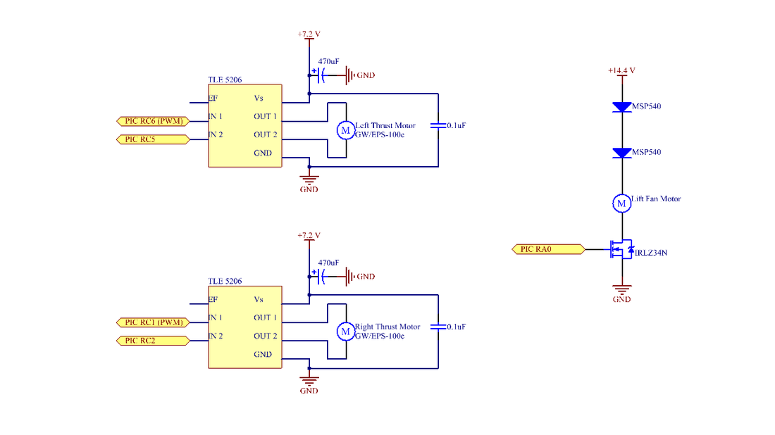
Motor Drivers
To drive the thrust/steering fan motors, we use TLE-5206 H-bridges. This allows us to implement bi-directional PWM control. The lift fan, however, requires only single-direction digital control. Thus the lift fan driver consists of an N-channel power MOSFET with two diodes to drop the voltage by a couple volts in order to safely power the 12V-rated fan from two 7.2 V NiCd batteries in series.
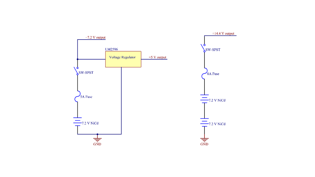
Power Distribution
Our power distribution layout involves two different circuits: one for powering the lift fan and another for powering everything else. The lift fan is powered by two 7.2V NiCd batteries in series. The thrust/steering fans are powered by one 7.2V NiCd battery. This battery also supplies a regulator that outputs 5V to all of the logical circuitry on the hovercraft.